Buy PCB's Kits and Components for Audio Amplifiers Pre Amps BT boards Power supplies solar charge controllers Vu Meters & electronics parts at best price
- (+91) 9424930058
- mypcbinfo@gmail.com
- Amphead Electro Works, Aashish Complex, Ward No. 03 NH-46, Itarsi, Itarsi, Madhya Pradesh, India. 461111
© 2020 MYPCB. All Rights Reserved

100 watts of Hassle free audio power
New Version of PCB having space for fitting heatsinks easily.
Now you can fit Many Types of Heatsinks on the PCB or Fit many pcbs on a big heat sink to make 2.1 or 4.1 or 5.1 Amplifier.
What TUSKER has achieved in this short period is exceptional.
Tusker is simple, easy to make and delivers high power with many types of speakers.
You may ask why the name “TUSKER”, after all it is a small pcb.
What can I say, small number of Tuskers ( Not the Truck, but Elephants ) still roam the forests of our country, they are Majestic.)
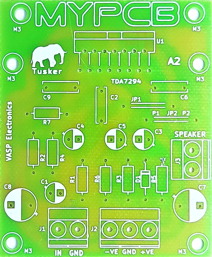 TDA7294 100w amplifier PCB Board
Features of TDA7294 Mono Amplifier Board
- High Output - 100 watt RMS output power using 8 ohms speakers.*
- Low Distortion - 0.1% Total Harmonic Distortion at 20 watt output using 8 ohms speakers and 1KHz sine wave input.*
- Speaker usability - 4 & 8 ohms, 50 watt to 200 watt speakers can be used.*
- Supply voltage - 12 volts to 40 volts DC supply working range.*
- Standard Components - All components used are available online or at your local electronics store.
- No SMD components used - Only through hole components used, making soldering and replacement hassle free.
- Low cost - This amplifier can be made in a fraction of cost compared to similar amplifiers available in market.
* as per TDA7294 STMicroelectronics datasheet.
Tusker TDA7294 amplifier board to make your own -
- Home Theater System - 300 watts of power with 3 Tusker boards to make 2.1 amplifier.
- Subwoofer Amplifier - High power amplification of low frequency sound.
- Musical instrument amplifier - Frequency response 20 Hz to 20 KHz, you can amplify any instrument like Guitar, Keyboard, Banjo.
- Amplified speaker box - Compact size board that can be fitted inside the speaker enclosure.
- Stereo Amplifier - Listen to your favorite songs in clarity never experienced before.
Brief Description of TDA7294 amplifier circuit :-
CLICK HERE to download TDA7294 Amplifier circuit diagram
The circuit is quite simple, main job of amplification is done by ic U1 and rest are the supporting components.
Input signal is fed to pin no.3 (Non Inverting Input) through R1 & C2. R7 defines the input impedance.
R2 & R4 connected to Pin no.2 (Inverting input) set the closed loop gain. Changing the value of any one these resistors will change the gain of the amplifier.
Pin no.9 (Stand by) - R6 keeps ic U1 in active mode by providing positve voltage.
Pin no. 7, 13 are positive supply, Pin no. 8, 15 are negative supply and 1, 4 are ground pins. Pin no.14 is the output pin.
Mute Function - Pin no.10 (Mute) is connected to JP2. To use the mute function replace JP2 with a switch.
Metal Tab of ic U1 is connected to negative supply internally, so proper insulation is necessary when fitting ic U1 on heatsink.
Compatible / Replacement Part no.with Datasheet download links.*
PCB Specification
- Type of PCB - Single sided, Glass Epoxy FR-4 Grade A
- PCB Size - 58 mm x 54 mm (2.3 inch x 2.1 inch ), pcb Thickness - 1.6 mm.
- Thickness of copper on PCB - 35 micrometer
PCB designed with thick copper tracks & large solder pads to facilitate straightforward placement and soldering of components.
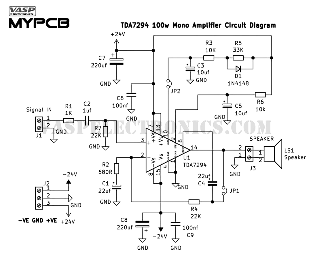 TDA7294 100w amplifier circuit diagram