Buy PCB's Kits and Components for Audio Amplifiers Pre Amps BT boards Power supplies solar charge controllers Vu Meters & electronics parts at best price
- (+91) 9424930058
- mypcbinfo@gmail.com
- Amphead Electro Works, Aashish Complex, Ward No. 03 NH-46, Itarsi, Itarsi, Madhya Pradesh, India. 461111
© 2020 MYPCB. All Rights Reserved

A Short Story
Once upon a time there was a guy named Mohan, one day his amplified stereo speakers stopped working.
Out of curiosity he opened the speaker box, inside was a pcb with many electronic components and wires.
At first he thought so many parts & wires, how I am going to replace it, but he was clever like a fox.
So he searched the internet for similar pcb board and found many boards but nobody is explaining how this thing works and how you can make it yourself.
Then suddenly one board caught his eye, and it was ( you guessed it right ) FOX2. Rest is history.
Moral of the story – Electronic circuit boards are not made by aliens, anyone can make them.
Features of TDA2030 2050 Stereo Amplifier
- High Output Power - 20 + 20 watt RMS output power.*
- Very Low Distortion - 0.5% Total Harmonic Distortion at 15 watt power output using 8 ohms speakers and 1K Hz sine wave input.*
- Speaker usability - 4 & 8 ohms, 5 watt to 50 watt speakers can be used.
- Supply voltage - ±12 volts to ±22 volts DC supply working range.*
- Standard components - All components used are available online or at your local electronics store.
- No SMD components - Only through hole components used, making soldering and replacement hassle free.
- Cost effective - This amplifier can be made in a fraction of cost compared to similar amplifiers available in market.
* as per TDA2030A Unisonic Technologies datasheet.
Brief Description of TDA2030 Amplifier circuit :-
CLICK HERE to download TDA2030 amplifier circuit diagram
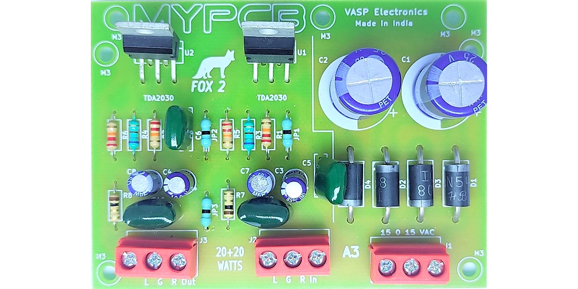
This circuit has on-board power supply rectifier made of Diode D1, D2, D3, D4. Capacitor C1 & C2 are used to filter the DC supply.
Main job of amplification is done by ic U1 and U2. Rest are the supporting components.
Following is the circuit description of ic U1. Ic U2 also works in similar manner.
Input signal is received on pin no.1 (Non Inverting Input) through C3.
R1 defines the input impedance.
R3 & R5 connected to Pin no.2 (Inverting input) set the closed loop GAIN.
Changing any one or both of these resistor values will change the GAIN of the amplifier.
Pin no.5 is positive supply, Pin no.3 is negative supply and no.4 is output pin.
Please note that the Metal Tab of ic U1 is connected to negative supply internally, so proper insulation is necessary when fitting ic U1 & U2 on heatsink.
Compatible / Replacement Part no. with Datasheet download Links*
PCB Specification
- Type of PCB - Single sided, Glass Epoxy FR-4 Grade A
- PCB Size - 96mm x 52mm ( 3.78 inch x 2 inch ), PCB Thickness = 1.6 mm
- Thickness of copper on PCB - 35 micrometer
PCB designed with thick copper tracks & large solder pads to facilitate straightforward placement and soldering of components.


